Building the PicoEMP EMFI Tool
The ChipSHOUTER PicoEMP is an electromagnetic fault injection (EMFI) tool by NewAE that is available as a do-it-yourself project.
Consulting
I’m a freelance Security Consultant and currently available for new projects. If you are looking for assistance to secure your projects or organization, contact me.
Introduction
What is EMFI? By applying a short electric pulse through a coil, a localized and strong electromagnetic field can be generated. This field injects voltages into inner parts of electronic chips that are near some parts of the coil, which triggers all kinds of side effects that the chip designers did not expect or want to happen. For some processors, EMFI can be used to alter the program behavior in ways that are interesting from a security perspective, such as skipping CPU instructions.
There are other fault injection methods like voltage glitching or clock glitching. Typically, they are based on interfering with electrical connections and components that are exposed outside of the chip. These techniques have a lot of value as well, and I use them via the ChipWhisperer (also made by NewAE), as described in other articles. However, there are a few significant differences of EMFI over those methods:
- The pulse acts contact-less and through material - although typically only within very short distances
- The pulse acts upon individual internal areas of the targeted chip
- There is a good chance of bypassing existing hardware protections against other fault injection attacks
As a result, EMFI can be used trigger some effects that are hard or impossible to reach with more classical techniques.
I saw the PicoEMP project release in January and quickly decided to build one. I ordered the PCB, PCB stencil and electronic parts for both the device and a number of custom coil probes. My choices were mainly based on the hardware bill of materials (BOM) recommendations in the project repository and what was available at electronics distributors at the time. Despite the component shortages, I managed to get suitable parts for everything.
Disclaimer
The PicoEMP generates ↯ high voltage ↯ and may permanently harm you, your environment or any electronics around it. The following build photos and remarks have not gone through exhaustive safety checks, so assume that they are wrong and use your own judgment. This article is not at all a step-by-step tutorial and there are many aspects of a DIY project that can go catastrophically wrong.
Without warranty of any kind. Build and use at your own risk.
PicoEMP Assembly
The assembly starts with the PCB. Due to known issues with the design files, the ordered PCB is missing the two milled slots near the high-voltage area and for the two enclosure tabs. I was able to work around those issues to still mount the safety shield (as explained later) but recommend checking twice if the PCB manufacturer in question correctly handles the design in the manufacturing preview.
The rest of the board looked acceptable, so I went ahead with the build.
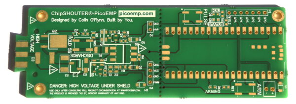
Note the missing milling in the left section between the white text sections and components area
Since most of the components are SMD parts, I ordered a matching solder mask stencil to distribute the solder paste.
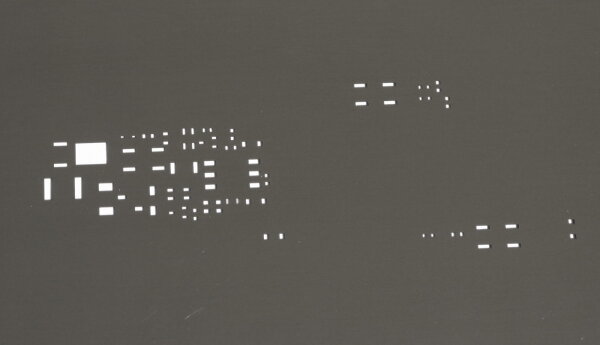
After adding of the paste, the PCB looks like this:
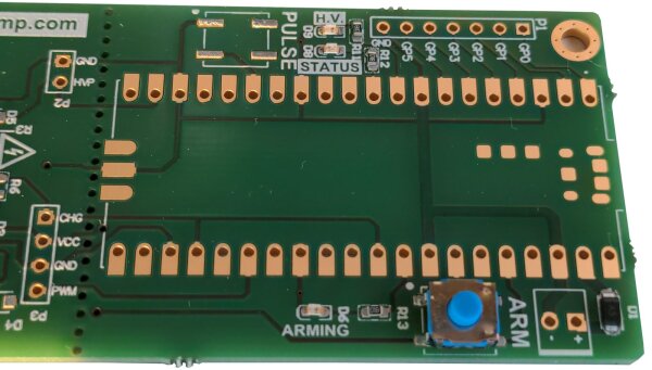
With the paste applied, I started to place the components for the right-hand side of the PCB. The large component footprint in the center is for the pre-made Raspberry Pico2040 board which I decided to hand-solder. It is not included in the solder paste steps and added later.
Build suggestion: watch out for the correct orientation of the LEDs, as they can look visually different on the front while oriented in the same way, and the silkscreen direction marking is easy to miss. I think the switches only have to be correct left-right and are wired identically on both sides, but you should check this out yourself.
After the components of the right-hand side were in place, I used a hot air station to melt the solder paste.
A proper reflow oven would be more reliable and consistent, but the DIY technique works for prototypes like this.
The SMD switches are sensitive to heat, so I will likely hand-solder them with a soldering iron next time.
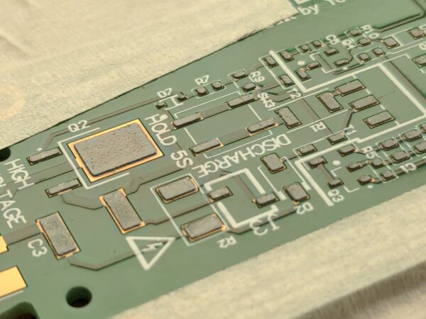
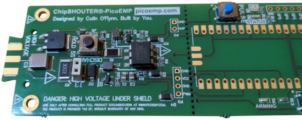
Next I started placing the components for the high voltage section.
Build suggestion: this requires some attention to detail, especially with the direction of the transformers, diodes and the phototransistor.
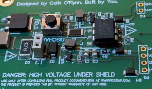
The hot air station soldering of the components went fine, except for the optional switch SW3 and pin connector J3 which deformed a bit in the heat, but they are still functional. As mentioned before, on potential future builds I will likely hand-solder these components to avoid heat damage.
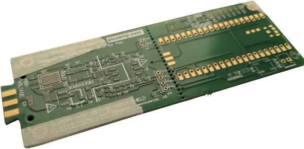
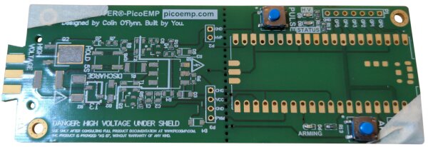
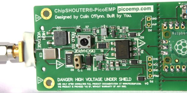
The next photo also has the SMA connector soldered on at the left board edge and protected with white shrink-wrap:
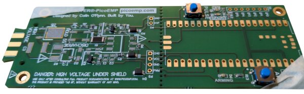
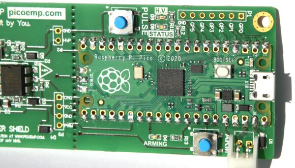
On the right sight of the PCB, the Raspberry Pico and the battery connector is soldered on:
Due to the milling issue, it was necessary to customize the protective plastic enclosure by stripping off its tabs. The screws that come with the enclosure don’t fit into the mounting holes properly, so I’ve used a pair of smaller screws that do not have this problem.
Build result:
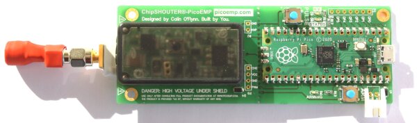
I’ve flashed the microcontroller with the C firmware, which worked without an external programmer due to the mass storage support. Up and running, the PicoEMP works and successfully glitches targets. Great!
The only bug I’ve noticed so far is that the arming button is unreliable on my unit. I think this is a software problem, but will re-check the electrical button behavior at some point to debug this further.
PicoEMP Probe Assembly
The previous section covered the build process of the main device, but there are additional parts required for fault injection, namely probe tips. I’ll show some of them here as well.
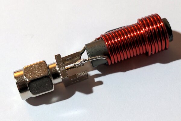
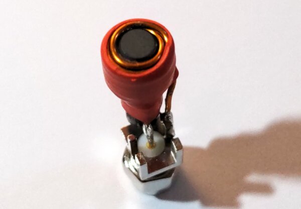
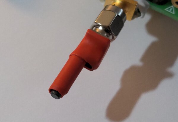
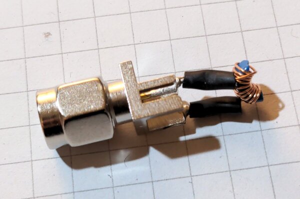
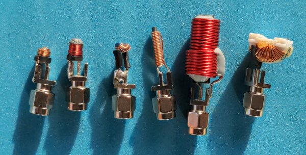
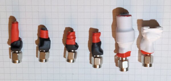
The PicoEMP can be fitted with a number of different electrical coil probes. It is important that they are exchangeable since otherwise the PicoEMP would be limited to one specific coil characteristic. In general, the probes are mainly designed around their SMA connector that allows easy swapping, the coil with its ferrite material in various configurations and some protective shrink wrap.
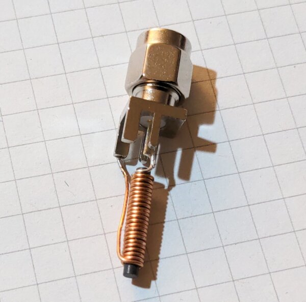
To summarize a complex topic, different coils are required for individual injection targets and use cases. The coil dimensions, coil type, number of windings, winding direction, number of layers, ferrite core form and other design aspects play a role in the strength and size of electromagnetic field that is generated. The physics details go beyond this article, but the injection tips section of the upstream documentation is a good place to start if you’re looking for component ideas.
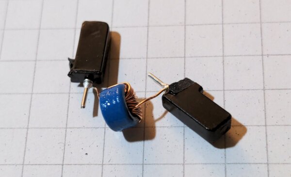
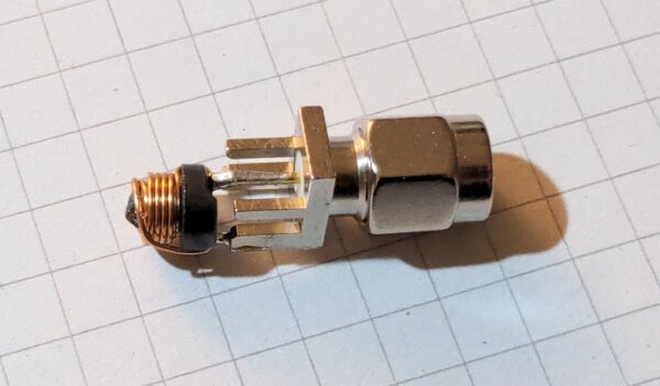
Here are some probes in various stages of assembly:
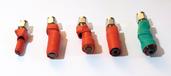
For my second set of custom probes, I decided to try out different variants of designs and also include some physically smaller probes for more accurate injections.
Summary
The PicoEMP is a really interesting DIY tool for advanced uses in hardware hacking, and I think it is great that it is available under an open license and accessible. The DIY nature of the tool also means that you have to get your hands dirty to get one (at least at this stage). Since the complex subject of EMFI needs a lot of experimentation time in any case, there are benefits in getting to know the low-level details of the device operation and probe design.
I have some future plans and ideas for potential tests of the device and experimental improvements, which may give some material for a second article at some point in the future.