PhyWhisperer Device Repair
The journey of repairing a NewAE PhyWhisperer USB module with the help of a thermal camera and some hot air reworking.
Contents
Consulting
I’m a freelance Security Consultant and currently available for new projects. If you are looking for assistance to secure your projects or organization, contact me.
Introduction
The PhyWhisperer is a special tool for USB-related hardware security research. Its main selling point is the ability to quickly sniff and trigger on USB packets at USB 2.0 speed through the use of an FPGA, which is difficult to achieve with other tools in this price class. While computers can sniff their incoming and outgoing USB traffic fairly easily, the typical delays make it difficult to act upon that information with other equipment. Like other tools from NewAE, the PhyWhisperer is very open and both the software and the hardware schematics are public, which I think is really useful for complex equipment.
For this article, the most relevant functionality of the hardware is to turn the 5V USB target power supply on and off based on software control from the host computer. This is just a side feature, but very useful during research if frequent USB device restarts of a target device are required.
I used the PhyWhisperer in this USB power switch role while experimenting with voltage glitching based fault injection on a connected USB target via the ChipWhisperer device. The ChipWhisperer glitch line was directly hooked up to the “Shunt Out” port and I used a custom variable shunt resistor. Due to errors in the glitching setup, the PhyWhisperer was exposed to quickly repeating voltage glitches on the target’s USB power supply line for some time that periodically shorted 5V USB to ground over a ~3 Ohm resistor.
I expected the PhyWhisperer to be robust against this sort of condition given its design, after all the internal components (described later in the article) are designed to detect and limit repeated short circuits without going up in smoke, but unfortunately that was not the case. One of the takeaway messages is that while the intended use case of the PhyWhisperer includes some basic side channel measurements over a voltage shunt right in the device, that port is not designed to be used for fault injection.
After the mentioned incident, my PhyWhisperer unit did not work correctly anymore. The main symptom was the inability to power the USB target via the external USB port. So the natural next step was to open up the device and see if I can repair it with the help of the existing public design documents, and learn more about the device and its limitations in the process.
Disclaimer: Using and repairing a broken device like this can be dangerous for you or your equipment, even if it “just” involves 5 Volt DC. Do this at your own risk.
Repairing the Device
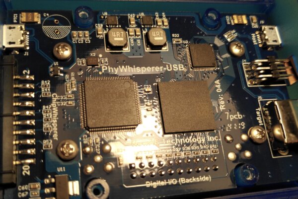
Main chip components center left to top right: Atmel microcontroller, Xilinx FPGA, SMSC USB PHY
Searching for Defects
My first round of analysis was based on a visual inspection and some limited electrical probing of the PCB, focusing on the polyfuses, USB-related traces and components as well as power regulators, since they were potentially stressed to a breaking point.
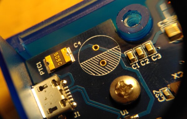
J1 and nearby components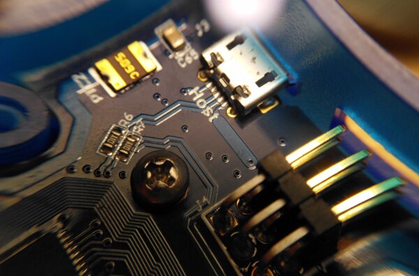
J3 and nearby components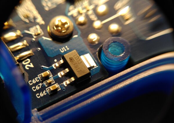
U11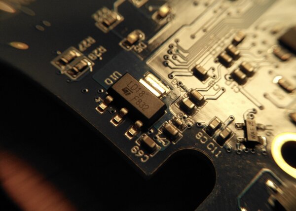
U10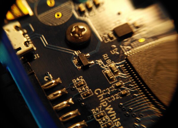
U1 near USB connector J1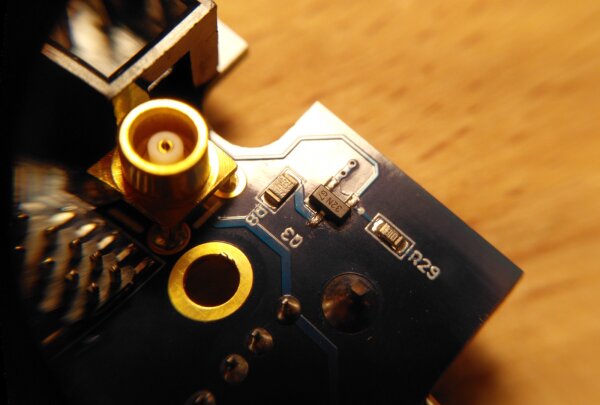
Q3Thermal Analysis
My initial inspection didn’t show any obvious damage. I thought about checking some of the electrical characteristics of essential components and voltage rails, but this is very time-consuming.
For some faults, one can take a debugging shortcut by checking the device with a thermal camera. The basic idea is to identify for misbehaving components, partial shorts and other issues by looking for unusual heat spots on the PCB while it is in operation.
The camera used here is “just” an entry-level Seek Thermal Compact camera that plugs into a smartphone.
It has a lot of sensor noise, general design limitations, unreliable absolute temperature readings and a mediocre smartphone application, but the manually adjustable focus and decent pixel resolution (for its price range) still make it interesting for this sort of occasional device analysis.
In the following grayscale images, bright pixels indicate higher temperatures, while darker pixels indicate lower temperatures or reflective metal surfaces. The absolute temperature readings are unreliable.

Those are all expected heat sources with no obvious anomalies.

U10 voltage regulator to the left and an unexpectedly hot component on the bottom of the image.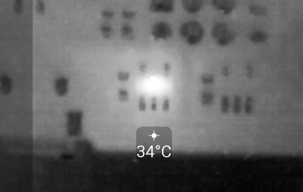
Analyzing the Defect
Closer visual inspection shows that clearly something isn’t right with the U4 component from the last thermal image.
Following the surrounding traces suggests that it is related to the USB power switching functionality without even looking at the schematic.
Its chip package is warped, likely because the internal silicon shorted out, which would explain the heating when powered.
The package damage was not yet present when I first looked at the board and showed up during the intermediary testing as the chip heated up more.
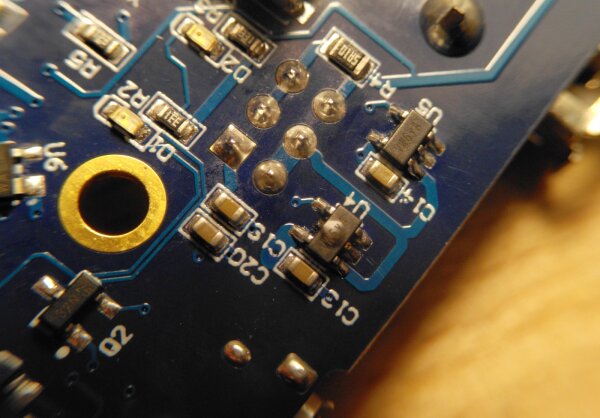
U4 chip marked VW6yA in the center right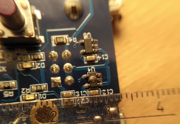
Repair No. 1
Knowing the broken component, I set out to learn more about the chip, find a spare and replace it. Additional electrical checks and remaining functionality suggested that the other chips of the device behaved normally.
The official schematic lists U4 and its twin neighbor U5 as the Diodes Incorporated AP22802 in a SOT-25 package.
Manufacturer datasheet description:
The AP22802 is a single channel current-limited integrated high-side power switch optimized for Universal Serial Bus […]
To summarize, the two switches control if the USB power to the target is supplied from the external connector (via U4), from the USB host that controls the PhyWhisperer (via U5), or none of those sources (= power off). In theory, both power sources could be enabled at the same time, but that would be a problem in case of any supply voltage mismatches, so the microcontroller control logic ensures at most one of the switches is active at any time.
Early in the repair process, I checked for alternative component options to see if there are other parts with a similar pinout that have additional protection features or lower current limits, but did not find any ideal candidates.
During this process, I noticed in the datasheets that the AP22802 may be problematic if used in a dual switch arrangement.
Similar to other high side USB power switches from other manufacturers that I looked at, its design assumes that it is alone on the USB power supply line and can always pull it to ground with a ~100 Ohm resistor when it is not supplying power on its own.
This discharge mechanism is used to empty any capacitors that are on the power supply line.
In the dual switch arrangement of the PhyWhisperer, a hard-wired discharge effect is counterproductive since one switch partially shorts out (~100 Ohm) at the same time that the other switch is supplying power. Additionally, the PhyWhisperer has its own dedicated circuit to do discharges if necessary, so the switches themselves don’t have to do this.
I reached out to NewAE via email to clarify if there is a known problem and if AP22802AW5-7 was in fact the right replacement part, but didn’t hear back from them until the first replacement part order arrived after some days.
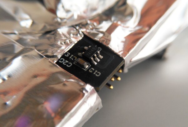
Therefore, I went ahead and replaced the broken chip via my hot air rework station, hoping the replacement part would be good enough.
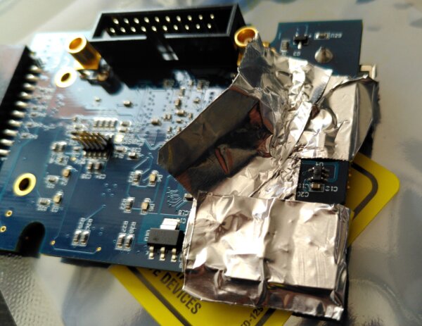
Better technique: adding a layer of polyimide (Kapton) tape under the aluminum tape avoids sticky adhesives on the PCB
Something is not Right
After replacing the broken component, the PhyWhisperer was working and USB target devices could be powered through U4 again. Yay!
However, something was still wrong after the first repair. In some switch configurations of U4 and U5,
specifically when U5 is supplying the power, the replaced U4 chip still got hotter than expected.
It wasn’t getting very hot, but the issue was clearly visible on the thermal camera.
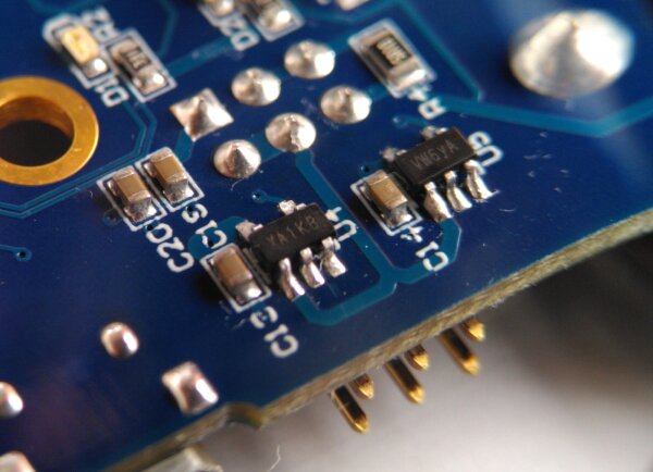
At the same time, I was aware of the fact that the new chip marking XA 1K B didn’t match the VW 6 yA I had replaced.
This all pointed to the previously discovered fact that the replacement part was likely suboptimal.
Additional datasheet searching confirmed that the parts number of what shipped with hardware revision Rev 04A corresponds to the Diodes Incorporated AP2171A switch that does not have the discharge functionality built in.
So the official NewAE schematic was incorrect and used the outdated part number. Grr.
Schematics are not a great help during repair if they are leading people in the wrong direction.
To ensure I didn’t miss any important details, I wrote a post on the issue in the official NewAE forum. This was quickly answered and led me to errata documentation that confirmed the expected technical details.
After this, the path was clear for another order of replacement parts, this time the AP2171AW-7.
Repair No. 2
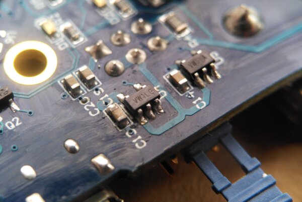
Once the second replacement component arrived, I did another round of hot air rework and replaced U4 again.
This time, the part number prefix VW matched the one it originally shipped with.
Summary
While the repair took a significant amount of time, technical deep dives like this can also be a chance to learn a lot about the capabilities and limitations of your equipment. This is especially helpful when using experimental equipment in more or less unintended or untested ways, which happens a lot during hardware hacking.
I have the impression that a future hardware revision of the device could be more robust against electrical fault conditions by actually checking the fault indicator pin of the USB switches and shutting down power in case of anomalies, but there may be other reasons why the existing design has not done this. I may revisit this topic in the future for other USB-related projects.
As a result of the repairs, my PhyWhisperer is fully operational again and works without internal heating short circuits, which I’m happy about. If anyone runs into similar issues in the future, I hope this article can shed some light onto the topic.