OLED Side Channel Observations and Mitigation
This article presents more details, measurements and observations for the OLED side channel issue that I reported back in 2019.
It also shows some data on the main mitigation technique that I evaluated during the disclosure.
I recommend reading the original blog article
and the SatoshiLabs article as an introduction to this topic.
More vendor articles are linked in the original article.
Please note that some vendors have rolled out mitigations via firmware updates. All measurements in this article are from archive data and represent the unpatched May 2019 firmware states unless noted otherwise.
Contents
Consulting
I’m a freelance Security Consultant and currently available for new projects. If you are looking for assistance to secure your projects or organization, contact me.
Observation Data
Trezor One
Let’s begin with an OLED screen that shows no secret information, but is useful to demonstrate the effect:
The power consumption over time directly depends on the pixel intensity of each horizontal display row during the drawing cycle.
At ~86Hz refresh rate × 64 horizontal lines per display cycle for the Trezor One, things are happening at snail pace compared with other cryptographic side channels that for example influence a few dozen CPU clock cycles @120 MHz. Additionally, the Trezor One OLED screen draws up to ~100mW of power at full brightness according to the datasheet, which makes this effect difficult to hide via regular power supply filtering of the device.
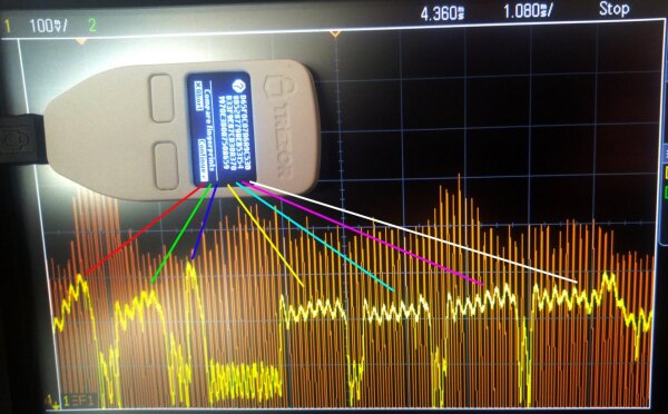
During testing, I made use of the custom Trezor homescreen background functionality to display custom test patterns with the unmodified firmware:
A special homescreen test pattern with left-aligned pixel rows is set to visualize the side channel effect and its scale.
KeepKey
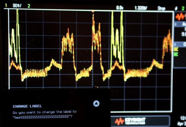
During the research process, I had to determine how well individual text changes could be detected. One time-saving trick for this was to use UI dialogs that show user-controllable text, which allows direct comparisons of similar screen contents without re-flashing the firmware.
Here is an image series for the KeepKey:
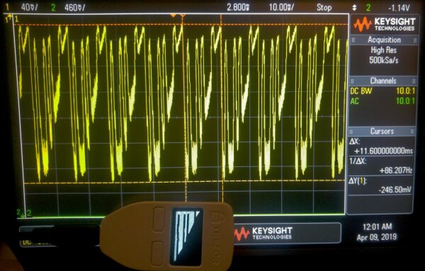
The first bump in the trace is caused by
CHANGE LABEL, the second by do you want to change the label to.In the second figure, the text 222 is added to the test label. Notice how this change is reflected in the right half of the oscilloscope trace over the previous measurement. The increase in luminosity in the label display rows is clearly reflected in the oscilloscope trace.
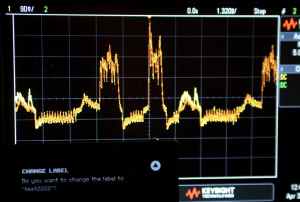
By adding a large number of 222 text segments, the effect can be shown in exaggerated form, see the strong increase in yellow. Other sections of the display trace are unaffected by the change.
Kasse HK1000
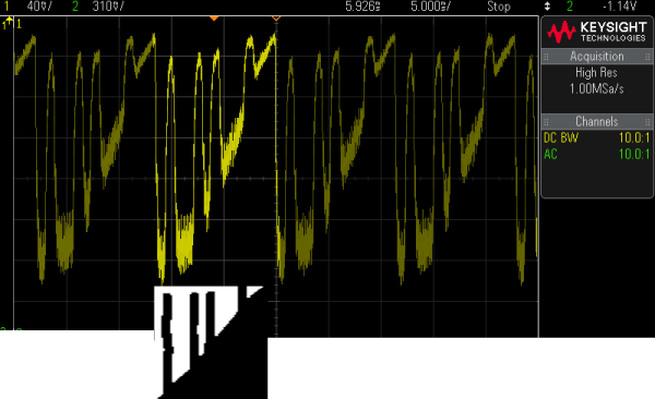
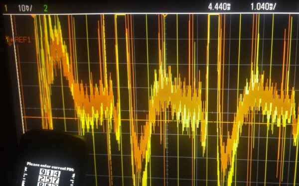
This overview graph shows multiple display refresh cycles for the Kasse HK 1000:
Different PIN entry states result in changes in the signal:
1 vs. 7Spectrogram Introduction
Some of the following figures contain spectrograms and waterfall plots that show the intensity of individual frequency components of a recording over time. Unlike the oscilloscope trace graphs, they are not a direct visualization of power consumption in a narrow time window of several milliseconds (a single display refresh). Instead, they can plot the calculated average frequency pattern over several seconds to several minutes of signal capture.
I have chosen this type of measurement during the issue reporting stage to show vendors that the side channel can indeed lead to observable differences in security-related user actions such as PIN entry. Due to the involved complexity and limitations of standalone oscilloscope data acquisition and transfer, it was not always straightforward to collect good statistics and measurements without significant engineering overhead or manual work. Additionally, I wanted to substantiate my assumption that an attack with much more limited data sampling and data processing capabilities than a bench oscilloscope was generally feasible. To do this, I focused on side channel effects in the lower kilohertz range, which can be sampled directly by low-power analog to digital converters and transformed into a basic FFT form via common microcontrollers.
This idea is somewhat similar to isolating and comparing spectral lines of characteristic light sources to differentiate them from each other, as it should become apparent from the included figures.
Ledger Nano X
Interestingly, the Ledger Nano X leaks information about its OLED screen if connected via USB C despite having an internal battery. Apparently, the internal battery is not used as the main power source when running on USB. This is probably beneficial for the battery endurance, but not for the defensive properties against information leaks.
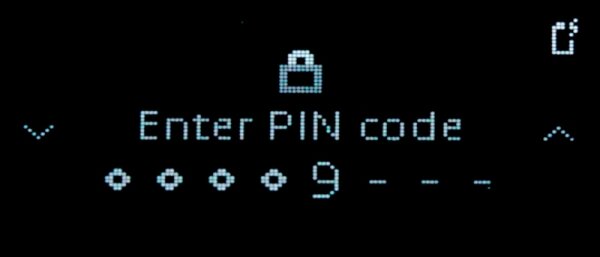
PIN Dialog
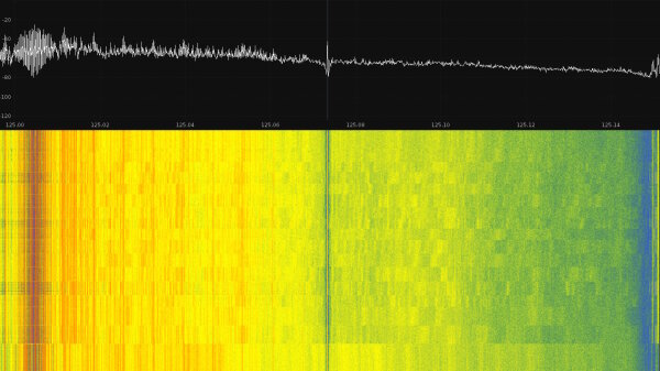
The following figure is a waterfall graph of different PIN display states:
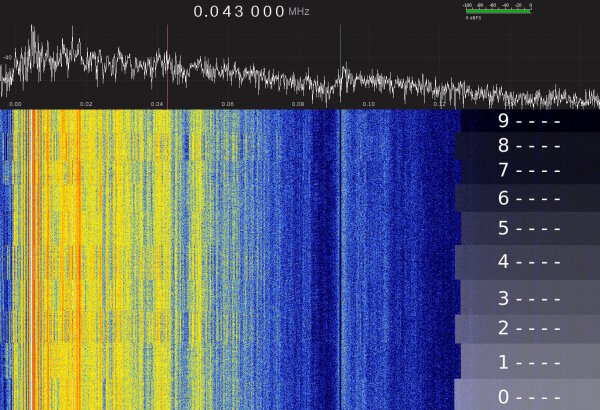
0------- to 9------- as marked by the overlay on the right.FFT waterfall diagram of SDR capture, USB line measurement, vertical time axis.
Hardware: HackRF clone and Nooelec HF upconverter to allow clean signal capture near 0kHz.
This SDR recording confirms that there are significant display-related changes in the electrical behavior below ~70kHz on the Nano X when entering PINs. The FFT frequency fingerprint of a given screen content stays fairly constant with no significant noise sources that interfere with the observation.
Notably, only one digit of the PIN is actually displayed at any time and confirmed digits are replaced by •, which helps with fingerprinting by keeping the number of variations small:
There are a number of redundancies which increase the chance of a correct detection:
- The user has to cycle through PIN digits one at the time
- The PIN entry shifts through numbers in a known order (example:
1 -> 2 -> 3or5 -> 4 -> 3to get to3) - The PIN is asked on each device startup (by design)
My goal was to create a proof-of-concept to show that the information leak can be captured without advanced (expensive, power-hungry, bulky) equipment. To achieve this, I used an off-the-shelf USB sound card to perform measurements that a malicious microcontroller setup could also do. For my experiments, I picked an Asus Xonar U7, but most soundcards with reasonable microphone input channel quality and sampling rates of 96kHz or higher should allow reproducing these results. Note that no acoustic measurement is done here, the input is directly used as a very low-end oscilloscope.
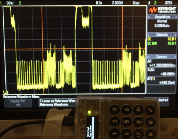
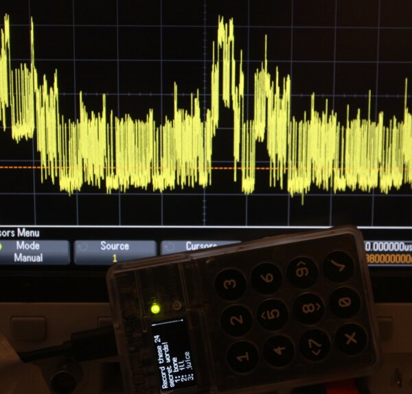
BIP39 Mnemonic Seed Word Dialog
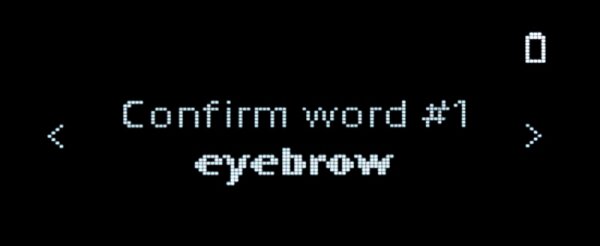
The mnemonic seed setup of the Nano X shows the secret words of the private key individually on the screen, as seen here on a confirmation dialog:
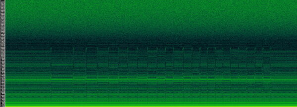
The following spectrogram records the full BIP39 setup in the 0 - 48kHz range. Each of the 24 seed words is visible for about 5 seconds before moving to the next word. At the end of the recording, the “Press left to ..” text dialog is shown.
As you can see, the 24 individual “spectrum fingerprint” patterns of the secret words stand out:
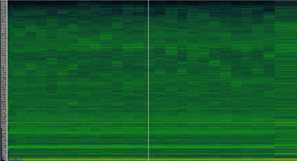
FFT spectrogram, horizontal time axis, 150s.
Xonar U7 @ 96kHz, USB line measurement
There is a lot of engineering work necessary to go from this POC to usable attack hardware, firmware and corresponding data postprocessing toolchain. This was out of scope for the disclosure.
In my opinion, it is generally plausible that a database of all BIP39 word “fingerprints” can be created to identify individual words with reasonable accuracy.
Let’s suppose that a malicious implant has taken good measurements during the setup and was successful in exfiltrating that data to a remote attacker. If the attacker manages to identify most of the seed words (for example with one or two bits of uncertainty per word on average) then there is a good chance to bruteforce the exact cryptographic private key in an offline attack and steal the funds. So far, this is a hypothetical worst-case scenario, but it is an ugly one.
Since this attack requires malicious hardware in attached USB equipment, my personal recommendation for cautious Nano X owners is
- Charge the battery to 100% before the initial setup.
- Avoid USB connections during the setup.
Running on a trusted internal battery is a strong defense against power consumption-based side channel attacks of this type.
Note: the measurements presented here reflect the original device behavior in May 2019. During the disclosure, Ledger planned firmware mitigations to mask the side channel.
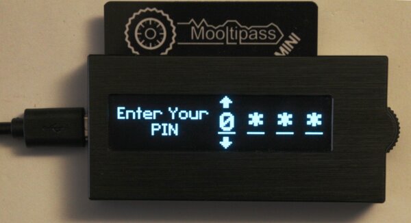
Mooltipass Mini
The Mooltipass hardware password manager is an interesting device. It was built by an open source community, which is one of the reasons why I invested the extra time to analyze it and extensively discuss the side channel with its main creator Mathieu Stephan. Unlike the hardware wallets, there are no cryptocurrency funds at risk with this device. Since the protected passwords are transferred over USB HID by design, it is arguably not meant to defend against a hardware USB man-in-the-middle attack. However, by recovering the PIN, an attacker might still gather valuable, rarely used passwords that are not available via other attacks.
The basic OLED power draw is clearly visible when looking at multiple OLED refresh cycles:
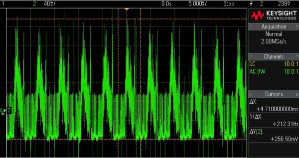
Note the higher display refresh frequency of about 212Hz.
But does it leak sensitive information? I suspect that it does.
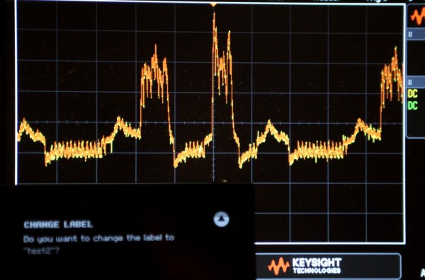
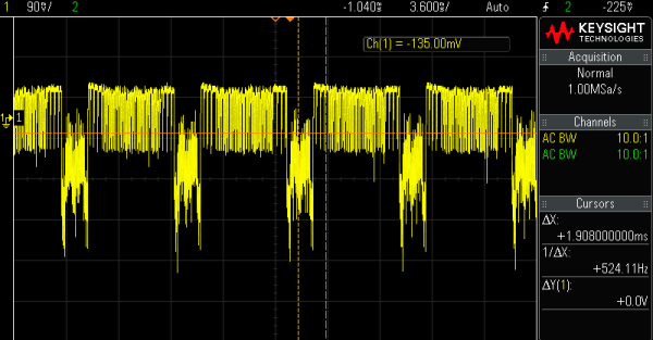
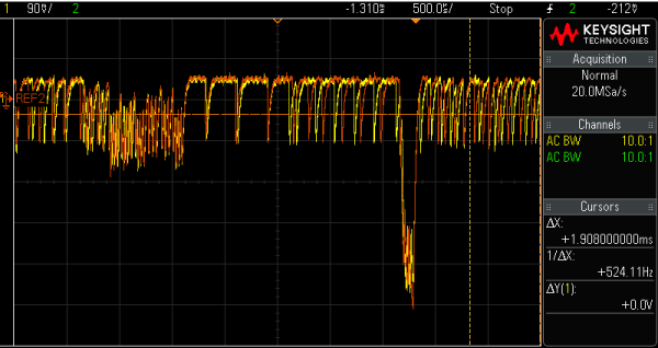
The side channel is mainly relevant for the digit-by-digit PIN entry dialog. It replaces all other digits by *, which simplifies comparisons:
Schematic overlay of the PIN entry with the oscilloscope trace:
Display rows highlighted in red contain information about the PIN digit.
When looking closer at the sensitive pixel area and comparing two particular digit values, the traces differ in the expected region. This makes it generally plausible that a few pixels per row difference can actually be measured by interpreting those changes.
0 * * * (orange) and F * * * (green) plus screen overlay.Highlighted in red are horizontal display rows which contain sensitive information about the PIN digit.
However, the power consumption pattern is clearly more complex than that of other devices and it was debated whether the observed differences were leaking information.
To show that the side channel does cause information leakage during the PIN entry, I again turned to FFT spectrograms:
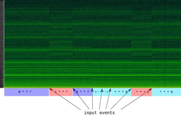
0 and 1 digit at various positions.Xonar U7 @ 96kHz, USB line measurement
One can see that PIN states can be differentiated from each other.
A second analysis of different PIN states on a broader frequency spectrum confirms this:
0 to F, range 0 to 150kHz.Hardware: HackRF clone and Nooelec 125Mhz upconverter
I regard it as proven that individual PIN digit values have a stable, consistent side channel characteristic on the Mooltipass and can be differentiated by an attacker. In my opinion, this can be exploited in hardware to reconstruct the PIN. Arguably there is much less potential reward for an attacker compared to hardware wallet targets, and it is necessary to get physical access to the Mooltipass smartcard to extract the secrets.
Whether or not you consider real-world attacks that use this side channel on the Mooltipass Mini to be realistic depends on your thread model. For most scenarios that involve high-value targets and malicious hardware, there are probably easier ways to do defeat the PIN protection, for example by replacing the whole Mooltipass device with a backdoored unit (custom firmware or hardware) during shipping.
During the disclosure, I received a custom firmware that effectively masked the PIN entry with additional pixel patterns based on the general “mitigation A” approach mentioned below. To my knowledge, this firmware is not rolled out, but available to customers on request.
Coldcard Mk1
Here is the basic side channel on the Coldcard:
A few observations:
- The OLED display is drawn top-to-bottom
- Strong signal amplitude, notice the 90mV/div
- About 89Hz OLED cycle rate, similar to other wallets
- BIP39 words are shown as a scrollable list
Since there is only one BIP39 seed word per line during the setup, it appears generally plausible to me that they can be differentiated in principle, although not with a FFT over the whole display:
Note: the measurements presented here reflect the original device behavior in May 2019. After my disclosure, Coinkite has introduced a firmware mitigation to mask the BIP39 words.
Mitigation A: Removing Line Brightness Differences
Okay, say a given hardware security device uses a row-based OLED screen, is powered from a potentially bugged power supply circuit and wants to display secret content from time to time without leaking information. What now? Are there ways to work around the problem?
During the disclosure, I recommended the “mitigation approach A” that was implemented in the Trezor firmware 1.8.2:


To summarize, the concept of this mitigation approach is to shield sensitive display sections against leakage by adding the right number of decoy pixels on each row to average out the number of white pixels. If the horizontal line average is identical regardless of the secret then the power consumption carries no problematic information. Obviously, this requires visual changes to sensitive screen areas, which not all vendors are willing to do.
Here is a collection of spectrograph recordings with the Trezor One that shows the general potential of this approach.
First a BIP39 setup without the mitigation:
(suppressed word number display via modified firmware)
Xonar U7 @ 44kHz, USB line measurement
And here with the mitigation:
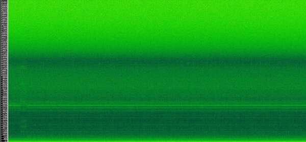
(suppressed word number display via modified firmware)
Xonar U7 @ 44kHz, USB line measurement
One can still make out some brief vertical lines in the recording, but those are caused by the screen animation between each seed word. Basically all of the FFT differences between the individual words have vanished in this recording, as intended.
Here is a direct comparison:
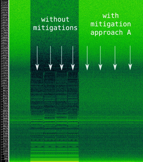
Xonar U7 @ 44kHz, USB line measurement
Not too bad for a fully software-based countermeasure, I would say.
Here is another measurement to compare an experimental variant of the masking for the shuffled PIN entry:
10mV / div zoom level.
Mitigation B / Mitigation C
Ledger and Coinkite have introduced their own firmware mitigations, but I do not have comparable archive data on them to include here.
Conclusion
Side channels can be complex and time-consuming beasts. The inherent engineering challenges makes them fascinating, but also hard to research. With hardware products, there are often multiple layers of undocumented complexity underneath that one has to grasp to understand observations and variations in the data.
Given that side channels are far cheaper to introduce and ignore than to find and fix, I am convinced that this class of security problems will stay with us for a while even as other technologies such as memory-safe languages get better and less dangerous.