Modding a Flashforge Guider II 3D Printer - Part 4
This article series documents a journey of modifying and improving a 3D printer. Part four is about a hardware mod that allows the use of a modern hotend in the old GuiderII printer once combined with the Klipper firmware, and why I made that modification.
Contents
Consulting
I’m a freelance Security Consultant and currently available for new projects. If you are looking for assistance to secure your projects or organization, contact me.
Disclaimer
Modifications to any 3D printer come with a serious risk of electrical problems, fires, crush injuries, and other health hazards. This set of blogposts is not a tutorial or guide, just a collection of notes, which aren’t meant to be complete or tested enough to be followed blindly. Do any changes at your own risk. Expect them to burn your house down 🔥. You have been warned!
Additionally, by my understanding, the modification presented here is not compatible with the standard Flashforge firmware or mainboard, for example due to the different thermocouple sensor type.
Flashforge Modding
Motivation
As described in part three of the series, the creative hardware hack use of a spare part (plus a whole lot of other work) finally allowed me to rebuild my Flashforge GuiderII printer with new controller electronics and the Klipper firmware while keeping the original stock extruder.
After working through a lot of experimental Klipper configurations and various hardware modifications (including switching to a PT1000 based hotend temperature sensor, custom endstop sensors, and other workarounds), I was finally able to do some first real prints and began to explore the printing speed and other Klipper tuning features. Given the modding complexity to get to this point, I was very likely one of the first people to run Klipper with the stock GuiderII extruder head hardware, and there wasn’t much out there in terms of data, references or recommendations.
Unfortunately, the resulting quality with quick printing settings of fast movement + large layer height was underwhelming. It took me a while to pinpoint the exact technical cause and rule out some modification-related issues.
Long story short, the maximum volumetric flow rate that the GuiderII printhead can supply with a standard 0.4mm brass nozzle is very low. To translate this to layman’s terms, it means that once the printer head moves quickly and extrudes a lot of plastic material, the supply of hot plastic can’t keep up with the demand, and too little plastic comes out. This is called underextrusion, and it causes various quality and reliability problems. Underextrusion is non-linear and can’t be solved properly with calibration or by using overcompensated settings, as they’ll just lead to overextrusion during other print phases instead.
The ellis 3dp print tuning guide has a great technical summary of this topic, as well as comparison values of the maximum volumetric flow rates for some well-known performance hotends. Running the extrusion tests via the “quick and dirty” method described there gave me some interesting insights, so I can highly recommend doing that to understand your own printer’s performance and limitations. Looking back, I attribute a lot of the printing quality problems and profile tuning difficulties I had on the stock firmware with underextrusion effects, which I didn’t properly recognize and understand back then.
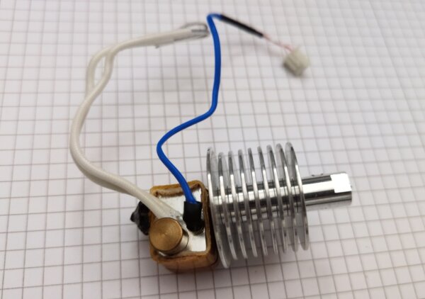
As described previously, I bought and fitted an improved Micro Swiss all metal hotend kit to my extruder, hoping it would improve the performance over the stock PTFE tube lined hotend - which, as it turns out, had partially failed internally already. It didn’t really improve much, and certainly not to the expected level. Like other performance problems I ran into with this printer, I attribute this primarily to the age of the design and lack of direct competition due to the closed system. When the GuiderII came out initially, and Micro Swiss designed their replacement kit, techniques such as a bi-metal construction, copper cooling fins, extra-thin tube walls with external support structure and so on weren’t common yet. Correspondingly, it aimed at a much lower performance target than today’s aftermarket hotends, and focused on high-temperature printing ability, which was probably enough of a selling point over the stock design.
I haven’t found any reliable vendor-supplied numbers or third party tests for the claimed volumetric flow rate of the GuiderII PTFE tube extruder, or its Micro Swiss replacement hotend. In the sales text description for a different and incompatible but roughly similar replacement hotend with MK10 dimensions, Micro Swiss suggests that the stock extruder of other Flashforge models is limited to 60mm/s movement speed “depending on nozzle size”. This doesn’t translate to any specific flow rate, but could mean a ballpark number of 5-7mm³/s if it applies for the 0.4mm default nozzle size and 0.2-0.3mm layer height. Based on the marketing description, the all-metal hotend should improve on this, but they also don’t specify by how much. Taking into account that plastic type, hotend temperature, heater block material and other factors play into this, I would roughly estimate that the all-metal hotend replacement on the GuiderII brought it up to 8-10mm³/s perhaps in my case, but not much more. Which was in the way of my plans to experiment with larger nozzle sizes, which need even more flow rate capacity.
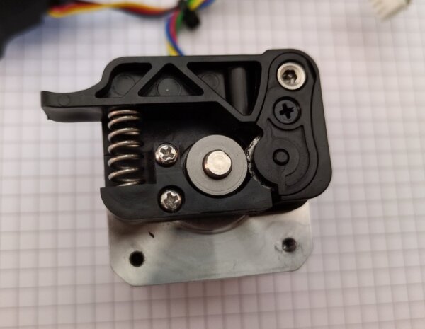
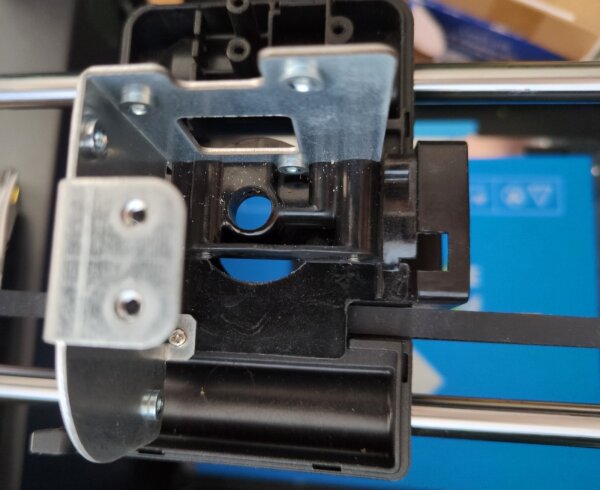
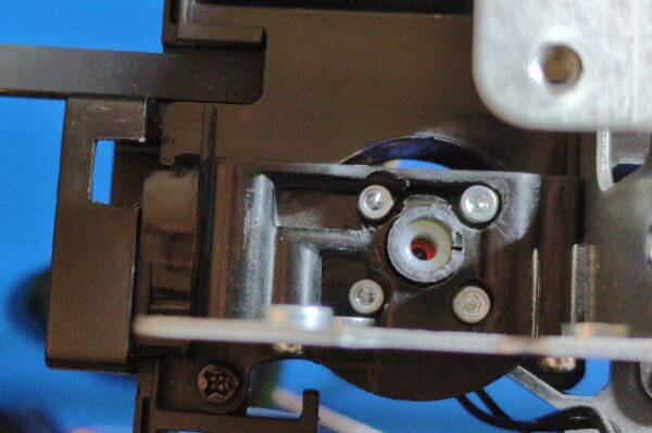
The GuiderII extruder head has a direct drive stepper motor without any gear mechanics, meaning it’s 1:1 coupled directly to the stepper shaft mechanically, unlike more modern extruder configurations with a gearbox. Additionally, it only grips the filament from one side, relying on spring tension and a bearing without teeth on the other side, instead of a two-sided feed system construction. I’ve switched the stock gear with a hardened replacement part, but this probably doesn’t do much to change any of its other properties aside from gear wear with abrasive filaments.
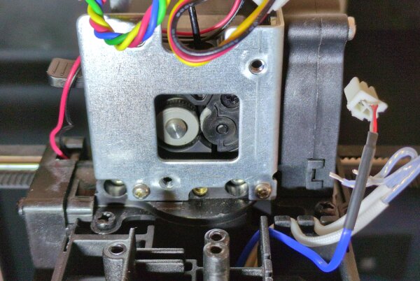
direct driven shaft on the center left, spring loaded bearing on the center right
This design puts it at an additional disadvantage for pushing lots of plastic through the hotend without slipping. I tried to compensate for this by using a better Trinamic TMC2209 motor driver for the extruder than the Allegro A4988 on the original mainboard, and experimented with different control settings and motor current restrictions. However, this only had a minor impact on performance - the hotend was clearly the limiting factor at this point. I considered fitting a different stepper motor, but didn’t think it would change much.
Not satisfied with the decision between extra-slow prints and underextrusion, it was time for more intense hardware modding.
Switching to a Different Hotend
Based on the previously mentioned ellis 3dp hardware comparison table, I investigated the different options with >= 20 mm³ of potential flow rate, taking into account that I would probably get less than that due to extruder gearing. The general idea was to somehow combine a modern high performance hotend with the stock GuiderII extruder carriage. Like before, I was in mostly unchartered waters for my printer, since not a lot of people had a reason to do this before. People modding the GuiderII either completely replaced the carriage, the whole X-Y system (very impressive), or stayed on the stock firmware which wouldn’t be compatible with the necessary changes.
I disliked the existing servo-mounted bed leveling switch design and contemplated replacing it with a more modern self-actuating probe. Unfortunately, finding the space to mount it rigidly in a not-too-warm spot near the extruder head on the stock extruder turned out to be difficult. For this reason, I aimed to re-use the existing bed leveling switch without modification, which imposed a maximum height restriction on the new hotend body. After all, the leveling probe can’t touch the printing bed if it’s shorter than the hotend + nozzle itself.
Looking at ellis’ list:
- the
MosquitoandMosquito Magnumwere top-end models around $200 which were too pricy to break during modding - the
Rapidomodels were too tall as a replacement - the
E3DV6andRevomodels were inexpensive, but not performing all that well, considering the modding effort
This brought me to the Phaetus Dragon series, in particular the Dragon HF (highflow) variant. The ultra high flow (UHF) variant is too tall, and the standard flow (SF) variant has a lot less throughput for just $10 less cost.
Helpfully, Phaetus has a Github repository with technical drawings for their different hotends, which was extremely useful during selection and planning. I measured various aspects of the old hotend, nozzle, bed leveling distance sensor, hotend chamber dimensions, and so on.
There was a possibility that the Dragon could fit as-is, so I went for it!
How to Mod Your Dragon (Hotend)
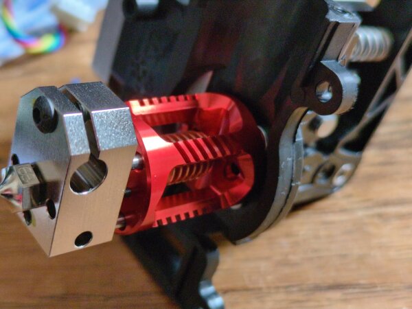
For my printers, my philosophy is “form follows function” and I don’t buy parts just because of their optics, but I have to admit that the hotend is looking really nice:
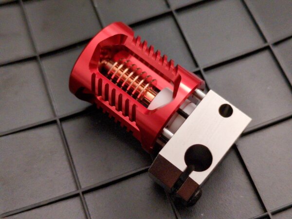
The exact model I bought is the Phaetus VORON Dragon High Flow Hotend, which as I understand is almost the same part as the normal non-Voron branded one, minus some unnecessary adapter parts and different colors.
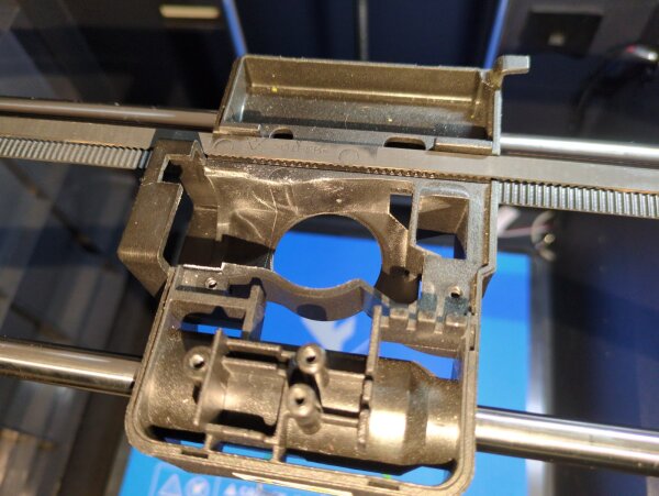
To understand what the mounting mod involves, we’re first looking at the GuiderII extruder carriage head, with the central plastic component and metal bracket still attached:
GuiderII carriage, from the extruder stepper sideFor comparison, this is what the empty carriage looks like, which holds the linear bearings and gets gripped by the belt. Fortunately, we can leave it as it is, and don’t need need to move it off the rails - which would require disassembling most of the printer X/Y axis mechanics.
GuiderII carriageWe’ll have to modify this center part, which is normally screwed into the main carriage frame, and makes up the top part of the central air cooling chamber around the hotend. The main risk of this modding experiment was that there are basically no spares available for the targeted part, short of buying a complete second used printer just to get another one. The high temperature extruder carriage upgrade kits of the GuiderIIs should (?) come with this part, but they cost around $200 and aren’t on stock anymore. Given that the targeted part is made out of plastic, it may be possible to print it, but that would probably require some more exotic filament materials to get the necessary stiffness and temperature resistance.
In other words, I only really had one good try at this.
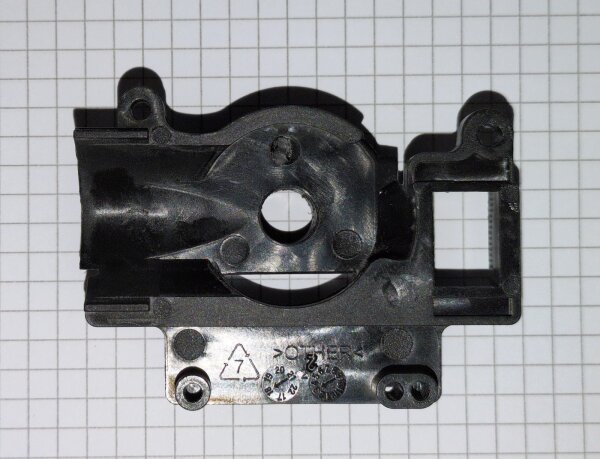
GuiderII carriage plastic center piece, bottom sideThe general idea is to use a rotating tool (Dremel) and drill to make room and drill holes for four screws which go through the center section. The Dragon hotend has four metric threads in the top for mounting, and the goal is to use those threads to firmly attach it to the printer head. Fortunately, it’s indeed possible to do this with regular metric screws and hex screw-heads with the right positioning, although the screws need to be cut to a custom length. I’ve added some metal washers as spacers to prevent direct contact between the plastic underside of the carriage and the top of the hotend, and also to help with an even positioning of the hotend. The stock hotend was clamped in via a differently method and was not flush with this surface, which explains the uneven finish left on this part. I smoothed this out a bit using the Dremel. In the center hole, I’ve installed a temporary placeholder tube part that’s meant to guide the filament from the extruder motor into the Dragon hotend.
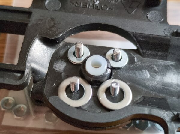
GuiderII carriage plastic center piece, modificationHere’s a top view with the new hotend mounted, showing the new screw heads sitting in the plastic at different heights, making up this square of mounting positions:
GuiderII carriage, modded center partA nice aspect about this modification strategy is that the Dragon hotend itself doesn’t need any physical changes, and can be removed for maintenance or re-used on other printers if needed.
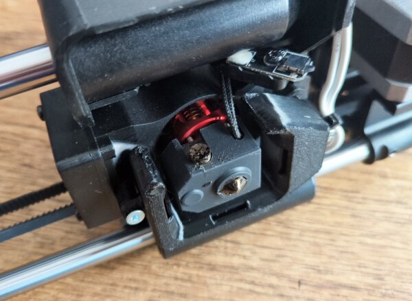
End result: it fits, and it prints!
As you can see, space for the temperature sensor cable and heater cartridge cable is limited, since they need to be out of the way of the sideways-rotating bed level sensor (top center, parked position), which required some creative re-routing:
The original GuiderII air shroud which distributes airflow from the parts cooling fan onto the print area wouldn’t fit anymore. I used an existing printable model for the air duct as the base for a custom cut-up modification which keeps three of the four sides, and manages to fit around the new and larger hotend bottom. There’s room for improvement here, but it’s already doing much better with any print that required parts cooling. Similarly, the extruder cooling fan airflow isn’t ideal yet. Closing off the bottom part of the inner cavity, like it’s done in the stock design, would ensure a cleaner left-to-right exhaust flow, and avoid unwanted cooling of the hotend block. However, this version works!
Summary
In this article, I’ve shown another part of my long journey on modding this GuiderII beyond some of its fundamental limitations.
Like in previous parts of this series, I have to emphasize that I don’t recommend going down this path, either for modding the stock extruder, or for doing a Klipper rebuild on the GuiderII in the first place. For every handcrafted, self-developed solution you build on this printer, you find half a dozen new problems that are costly or complex to fix. Being the first to engineer a solution can be rewarding, but it’s also a lot of extra work compared to a design which has an active community of many people doing so, as well as a good supply of spare parts and upgrades. In other words, if you like to tinker on this level, I highly recommend considering a Voron printer instead, or buy into another printer ecosystem with an active modding scene. There, you start with a modern, high-end design, lots of information, existing inspiration, and can take it from there.