Modding a Flashforge Guider II 3D Printer - Part 3
This article series documents a journey of modifying and improving a 3D printer. In part three, I’ll describe my approach for re-using the original Flashforge GuiderII extruder flex cable and extruder mount, and why this may or may not be a good strategy.
Contents
Consulting
I’m a freelance Security Consultant and currently available for new projects. If you are looking for assistance to secure your projects or organization, contact me.
Disclaimer
Modifications to any 3D printer come with a serious risk of electrical problems, fires, crush injuries, and other health hazards. This set of blogposts is not a tutorial or guide, just a collection of notes, which aren’t meant to be complete or tested enough to be followed blindly. Do any changes at your own risk. Expect them to burn your house down 🔥. You have been warned!
Flashforge Modding
The Extruder Flat Flex Cable Problem
As outlined in part two, the GuiderII uses a custom flat flex cable to connect the moving extruder head and all its components to the printer mainboard.
In short, it serves as a kind of umbilical cord between all of the electronics in the moving extruder head, including heater, fans, distance sensor, distance sensor servo motor, filament direct drive stepper motor, and temperature sensor:
[Extruder board] <--- flat flex cable --->  [Motherboard]
    |  |  |                                    |  |  |
    v  v  v                               drivers and logic
  components
On the mainboard side, the connection looks like this:
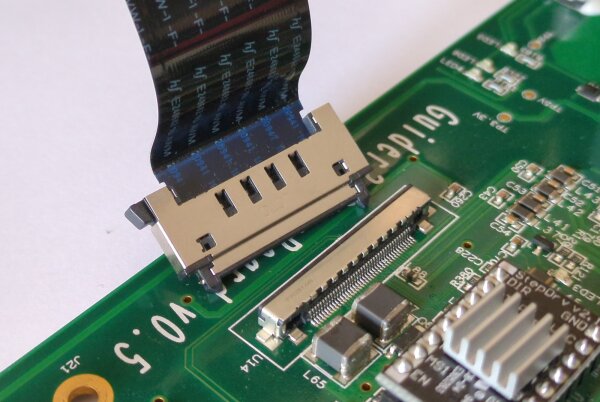
On the extruder head and carriage, it looks like this:
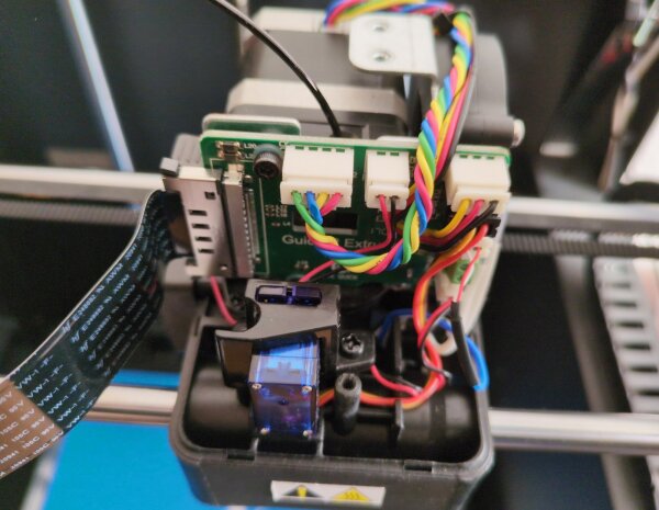
For my conversion of the GuiderII hardware to the modern Klipper system, I needed a way to interface an off-the-shelf replacement mainboard with the components in the extruder. At the time, building a custom cable harness looked difficult considering the required mechanical reliability (surviving the many back-and-forth motions without breaking). Since the original printer design used the flat ribbon cable in a suspended position, it didn’t have existing cable carrier mechanics in place. So I decided to go for the “elegant” solution of adapting and re-using the existing flat flex cable.
Warning: with hindsight, re-using the flex cable and extruder is an inferior solution and cost me a lot of unnecessary time and effort, for example when fighting with other pre-existing printing performance problems of the original extruder or electrical hotend thermocouple sensor problems. I do not recommend following my footsteps here. After hooking up the original extruder with some effort, it’s easy to fall into a sunk-cost-fallacy problem which involves costly extruder head related half-solutions.
Today, I think that ripping the original extruder equipment out and replacing it with a custom solution is a much better idea in the long run for many reasons. Crucially, there are some cheaper and more elegant options for this that weren’t as easily available when I started to go down the road of hardware modifications some years ago, for example using an off-the-shelf 24V & CAN or 24V & USB umbilical mod bundle.
A Solution to the Cable Problem
By swapping out the original Flashforge motherboard with a Raspberry Pi (running the main Klipper operating system) and a Bigtreetech Octopus Pro mainboard with the low-level Klipper firmware, I needed a way to get the electrical signals from the new mainboard onto the flex cable.
It may have been possible to design a custom “breakout board” PCB, identify and buy the correct flat ribbon SMD connector, solder the connector (fine pitch!) and hook it up to the new mainboard.
However, I realized:
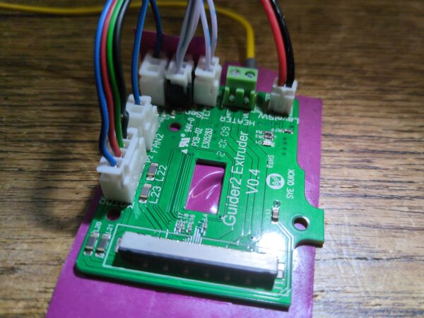
- The original
Guider2 ExtruderPCB is already effectively a breakout board and has all the connections I need - The original flat flex cable is flipped internally, making the same breakout board fit both ends
- The
Guider2 ExtruderPCB is officially available in shops as an inexpensive replacement part
In other words, there’s no need to go through the trouble of designing and ordering my own breakout PCB if the vendor already sells one. I’m proud of figuring this out, and seem to be the first person making use of this hardware hack from what I’ve found online.
Schematically, the new idea is:
[extruder board] <--- flat flex cable ---> [extruder board (mod)]
    |  |  |                                      ^  ^  ^
    v  v  v                                      |  |  |
  components                                 [new motherboard]
                                                 |  |  |
                                            drivers and logic
In practice, this still required a good deal of time-consuming hardware reverse engineering, double- and triple-checking, custom cable crimping for the new cables between motherboard and breakout board, and some selective PCB modifications. Electrically, several of the connections also aren’t ideal, for example because they involve more wire resistance and unshielded connections, don’t have decoupling capacitors close by, and so on. You also have to follow the vendor’s original pinout for the flex cable, with all its limitations.
However, this modification does work! Success!
Breakout Board Usage and Modifications
View of the replacement PCB:
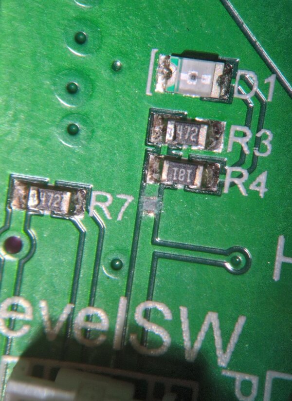
HET- GND not attached yet)It appears to be a constant with the Flashforge PCB designs that the diagnostics LEDs are integrated poorly into the circuits, causing unnecessary problems. In the case of the extruder PCB, the D1 LED leads to worse electrical performance of the level switch line, so I disabled D1 on both PCBs. Additionally, since the same circuitry is hooked up to a given electrical line twice by having the same breakout board on both ends, another change is necessary to keep the level switch working well. I decided to disable resistor R3 on the mainboard side PCB, but not on the extruder side PCB.
If you’re willing to go down this path, please do your own research about this and understand the circuit modifications before applying them.
Summary
The GuiderII models have a proprietary and custom flat flex cable, which is a major obstacle to turning this printer model into an printer running an open source system using common and popular commercial aftermarket parts. By re-using a spare part of the extruder PCB as a breakout board on the mainboard side, it’s possible to continue using the flex cable on a Klipper’ized setup. However, additional experience with the GuiderII shows that this solution brings many limitations, as much of the stock extruder is outclassed by more modern designs, forcing yet more GuiderII-specific modifications down the road.
For this reason, I don’t recommend this strategy. Complete replacements of the flat flex cable and extruder head are probably a better idea in 2025.