Modding a Flashforge Guider II 3D Printer - Part 2
This article series documents a journey of modifying and improving a 3D printer. In part two, I’ll outline some problems that I’ve encountered with the Guider II construction during modification.
As it is often the case, once you look closely enough at a complex engineering design, some bugs and problems become visible, which I’ve collected here.
Contents
Consulting
I’m a freelance Security Consultant and currently available for new projects. If you are looking for assistance to secure your projects or organization, contact me.
Disclaimer
Modifications to any 3D printer come with a serious risk of electrical problems, fires, crush injuries, and other health hazards. This set of blogposts is not a tutorial or guide, just a collection of notes, which aren’t meant to be complete or tested enough to be followed blindly. Do any changes at your own risk. Expect them to burn your house down 🔥. You have been warned!
Hardware Flaws and Bad Design Decisions
Overdriven Diagnostics LEDs
There are several different voltage rails on the printer mainboard PCB: 3.3V, 5V, 24V, and multiple 24V switched for different heating outputs, to name a few. The PCB designers included testpoints and green LEDs connected to these rails, which is really helpful since it allows distinguishing which outputs are active. The LEDs help debugging the electrical operation of a partially dismantled printer (the LEDs are normally not visible from outside the enclosure).
Unfortunately, on my Guider2 CoreBoard v0.5 mainboard, the PCB designers seem to have made a serious copy-paste or calculation mistake with the SMD LEDs and current-limiting SMD series resistors. As far as I can see, they’ve used plain 1000 Ohm resistors (marked 102) for those LEDs regardless of the voltage of the connected rail. This is fine for 3.3V and 5V, but leads to massive current and wasted heat on the 24V-connected LEDs.
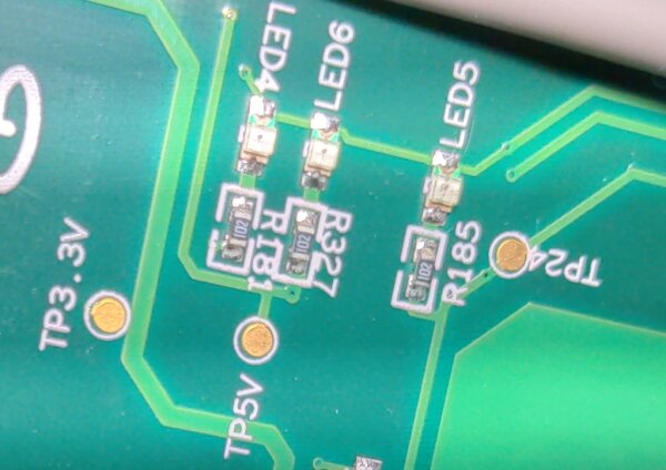

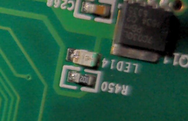
With about 1.8V of voltage drop over the green LED, the 1000 Ohm series resistor results in around 22mA of current through the LED. As a result, the LED is very bright and probably beyond the design specification at the expected high ambient temperatures, reducing the absolute lifespan of the LED.
However, the main problem is in the series resistor. It dissipates the rest of the electrical energy not taken by the LED. This is straightforward to calculate: 22V * 0.022A ~= 0.5W, almost half a Watt of heat on that SMD resistor part!
For context, the resistors are roughly in the 0603 standard SMD format (imperial), which means that they’re designed to take about 0.1W max under worst conditions and are driven five times as hard in reality. Given this situation, I think it’s only thanks to the two mainboard fans, which are blowing in the direction of the hot LEDs, that they’re not quickly failing left and right. I haven’t found accounts of failing Guider II mainboards due to this. Still, in the worst-case situation that one of those resistors shorts out due to overheating and the LED gets the full voltage, like 24V straight from the power supply, it’s going to be a bad situation.
Personally, I’ve left the LEDs circuits as they are while I was using the original mainboard, and mainly ensured they get plenty of cooling. Potential options for fixing this problem involves desoldering the LEDs or resistors to disable their function, or replacing the resistors with higher resistor values to properly fix their operation. (If you’re planning to do this, ensure you have a decent amount of SMD soldering experience and suitable equipment. The mainboard also has a mains AC connection and high current 24V, which is why you should be very careful about any soldering modifications)
Hot Optical Sensors
Unlike many other 3D printers, the X-, Y-, and Z- endstops use optical light barrier sensors combined with a special interruption bracket on the moving axis to detect the axis end positions. I like this fundamental concept, since it avoids some of the wear and crash-risk of mechanical microswitches.
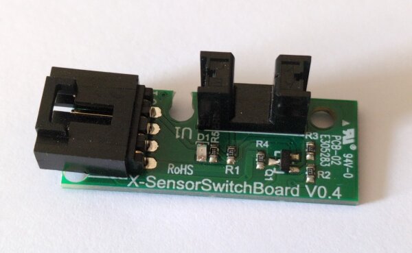
X-SensorSwitchBoard V0.4 optical endstop boardHowever, the custom sensor board that Flashforge uses seem poorly designed. Instead of using a photo interrupter (opto interrupter) part with a built-in transistor, they’re using a sensor that only has a diode, requiring a custom external transistor circuit to turn the sensor output into a clean binary signal that is fed to the mainboard.
It seems they fumbled this design, building a circuit that wastes a comparably large amount of power (about 100mA at 3.3V, so ~1/3W) once the printer is powered on and the light barrier isn’t interrupted. This power draw is a multiple of what the LED in the opto-sensor itself consumes for the basic operation, and makes the sensor boards heat up for no good reason. It’s not as bad of an electrical design problem as the diagnostics LEDs mentioned previously, but becomes fairly relevant when driving multiple of these boards with a custom new printer mainboard, since most printer boards usually don’t expect to supply a lot of current on the 3.3V rail. The endstop signal of these boards isn’t even particularly clean in terms of voltage levels, which can increase the chance of improper detections. I was unhappy about this, as sensor detection failures on the endstops can lead to mechanical problems very quickly if one of the axis gets driven beyond its maximum point.
As part of my major modifications, I’ve now replaced these sensors with other opto-interrupter boards which have a phototransistor, cleaner output, are 5V compatible, and avoid the power draw problem completely.
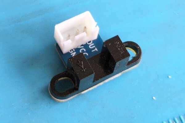
Quick warning: the optical sensor on the original SensorSwitchBoard modules has a reduced outer sensor tower width and -profile compared to those of other common phototransistor sensors on off-the-shelf parts, making those boards and sensors not fit in the same narrow screw mount spacing. This can be fixed carefully with a rotating tool (dremel), but requires special attention and care against shorted or broken sensors.
Suboptimal Fan Sizes and Cooling Design
The Guider II has several small 24V fans, namely:
- 30mm x 10mm axial fan for the extruder hotend cooling
- 50mm x 15mm blower fan for the extruder parts cooling
- two 40mm x 10mm axial fans for the motherboard cooling
- 40mm x 20mm axial fan in the power supply
I can partially understand the choices for the hotend, where space is very limited. A slightly less noisy 40mm x 10 instead of a 30mm x 10 extruder fan would have been nice, but their custom molded plastic case limited upgrade options here after the initial design.
The small built-in fan in the power supply can’t be changed, but notably it is internally temperature-controlled, so it’s not on full power all the time and only really loud when the bed heating is active, which draws the most power and heats the power supply.
What I was most annoyed about are the two unregulated motherboard cooling fans. I think it was a bad design choice to put the heat-sensitive electronics, including power supply and stepper drivers, effectively inside the heated build chamber instead of outside of it. Given this printer’s dimensions, they could have put at least some electronics in the unused open space under the printer, as it’s done in other large printer designs like the Voron series. Clearly, they wanted to keep all electronics behind the side cover for some reason. However, why not fully section off the electronics compartment on the right hand side of the printer and directly supply it with cool outside air from a slow-running 80mm or 120mm fan, instead of leaving these small fans to re-circulate hot air?
Looking at design drawings in the manual of the newer Guider IIs model suggests they at least added a small 40mm (?) fan which pulls cool air into the electronics compartment, which would confirm that they’ve also identified their original design as problematic. I’m not familiar with any details on this, though, and still expect the Guider IIs design to be far from optimal or quiet.
The positive efficiency benefits of treating the mainboard and power supply as additional chamber heaters are, in my opinion, definitely outweighed by the problems of having hotter-than-necessary electronics and louder-than-necessary fans. If the designers were concerned with dust and other contamination, they could probably have found a better solution with some kind of air intake filter.
My temporary workaround was to mostly run the 3D printer with one enclosure side removed, connecting a variable step-down voltage regulator to the 24V DC fan header, and running a 12V 3-Pin 120mm computer fan to cool the mainboard components. This leaves the build enclosure open and is not ideal, but was acceptable for the type of printing I did.
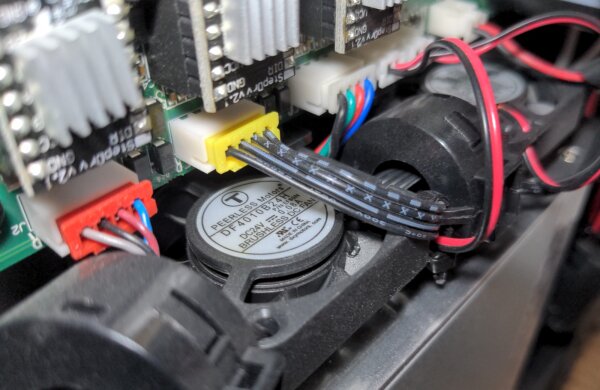
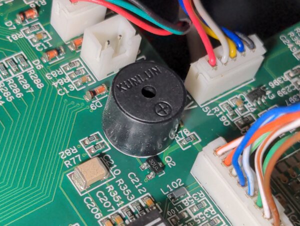
Noisy Buzzer
After some fan modifications reduced the fan noise of the printer when it was idle (not printing), I’ve noticed another unexpected source of noise: the black piezo buzzer on the mainboard was constantly driven by some kind of electrical interference, emitting a high-pitched noise that was previously hidden by the loud motherboard fans.
My low-tech solution: apply a short strip of tape over the speaker opening. This reduces the constant random noise enough to no longer be annoying, while still letting through most of the intended buzzer sounds and keep it functioning.
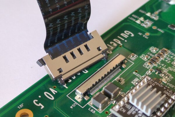
Limiting Hotend Flex Cable
The Guider II uses a special flex cable as the only connection between the hotend carriage and the mainboard. This represents a proprietary and custom interface that only a few other Flashforge printers share. Additionally, I suspect the different printer models using this cable have incompatible pinouts, and therefore incompatible mainboards + modules.
While I have to admit the flex cables were a novel and somewhat clever way to avoid the usual set of dragged regular cable looms, it’s also arguably somewhat of an Achilles heel once the special cable gets damaged, and totally obstructing many printer mods. Due to the custom cable and connectors, any more substantial modifications such as mainboard replacements also require completely different extruder head hardware if there is no way to interface with this special flex cable connection. Swapping in a different mainboard is already a huge task, but the flex cable is still making it significantly harder through direct and indirect restrictions.
I’ll go into more detail on how I’ve (mostly) solved this in a later post.
It should be noted that the flex cable strongly contributes to atrocious electrical conditions for data and sensor lines since they’re all pushed near the high-power PWM DC and high-noise motor lines. Additionally, the limited pin count forces many voltage rails to be shared among components, which causes a lack of spare control lines for extruder components. As a result, cleaner fan control via separate PWM control lines, fan tacho signals and other improvements such as permanently attached accelerometers on the extruder head simply aren’t possible.
Hotend Thermocouple Usage
As I found out during later parts of my modifications, the screwed (M3 screw) K-type thermocouple temperature sensor in the stock heater block is a really problematic design choice when combined with the flex cable electronic issues and a conversion chip located on the mainboard, not on the extruder PCB.
Thermocouples generate a few millivolts worth of signal from a special metal connection and require careful compensation of unwanted temperature-dependent effects in other cable junctions. In the Guider II construction, the flex cable electrical lines carrying this signal get absolutely hammered with injected noise (voltage spikes) from the parallel-running fluctuating currents of the extruder stepper motor once it is active, which is inherent in how stepper motors are driven. This leads to severe problems for accurate and reliable temperature readings from the thermocouple.
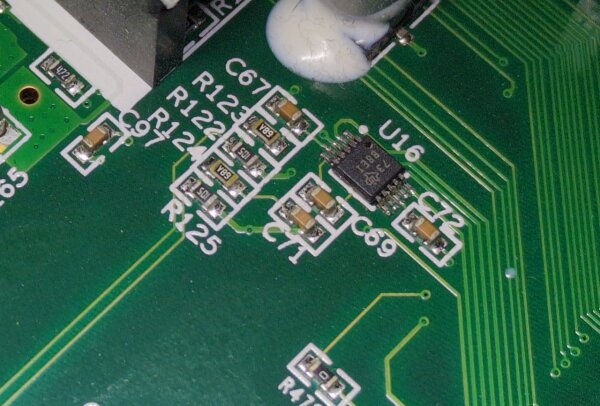
TI ADS1118 Analog-to-Digital converterFor custom printer modifications, the reliability problems persist even when using specially designed and Klipper-supported readout chips such as the MAX31855K on modules with passive LC filter components. On the original mainboard, the designers seem to have counteracted this to some degree via additional custom filtering and ADC conversion, but the noisy and polluted signal is fundamentally a self-inflicted design problem. For the hotend sensor, a cheap NTC 3950 type thermistor or a more expensive PT100/PT1000 thermistor would have been a much better choice to avoid these problems right from the start, since a resistive sensor is a lot less susceptible to this type of interference.
From my experience, at best, following this stock design with a K-type thermocouple and a MAX31855K readout module causes Klipper to go into emergency shutdown a few minutes into a print due to exceeding the allowed number of consecutive temp sensor readout errors. At worst, wrong readings could trick Klipper into overheating the extruder until something breaks or burns, which something you want to avoid at all costs.
Over the lifetime of my printer before the modifications, there was at least one incident where the firmware was operating with a false low extruder temperature reading (reading a low temperature when the extruder was actually hot), which is a very dangerous situation when actively heating the extruder. It’s possible this situation caused some of the damage to my hotend PTFE tube that I discovered later. While I’m not certain of the exact circumstances and performance in the original design, I highly recommend switching to a different hotend block thermometer type for any printer modification builds that allow it. Sticking with the original K-type sensor in this electrical configuration isn’t worth the hassle.
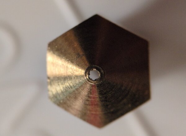
Semi-Custom MK10 Nozzle/Heater Block Format
Unlike most other printers on the market, the Guider II and its sister models use the MK10 type hotend and nozzle dimensions, which have standard M7 screw diameters on all hotend parts. This hasn’t found wide adoption among other manufacturers, which means that there are few quality upgrade and replacement options left available in today’s market for items such as high-quality nozzles of different sizes and materials. For the M6 screw diameters like E3D V6, Volcano, MK6/MK8 and so on, a lot more parts are available. With the benefit of hindsight, supporting one of those standards or allowing a conversion to it would have been better for end users for parts that eventually fail or wear out.
Additionally, the Guider II variant of the hotend heater block appears to be a cut down version of what other vendors use. The standard MK10 replacement hotend blocks that are still available online are larger than the original, interfering with the Guider’s stock part fan cooling attachment due to being a few millimeters wider and longer. This was annoying to find out and underlines the negative effects of shrinking official Flashforge parts supply.
Similarly, the Micro Swiss vendor sells an all metal hotend kit specifically meant to replace some parts of the official Flashforge hotend, to get rid of the PTFE parts and enable higher print temperatures. While it’s great that this is still available, I found out after installation that it’s actually not 100% compatible with the Guider II. The upper part that screws into the cooling fins adds a non-negligible height to the overall hotend assembly, leading the nozzle to sit over a millimeter further down. While this may not sound like much, it violates the assumptions of the original firmware about the nozzle position and reduces the distance to the bed leveling sensor, which creates new headaches. It’s also an old design without optimized bi-metal heatbreak materials, and overall didn’t perform as well as I hoped.
After spending some money on MK10 replacement parts, I’ve decided to go a completely different route to migrate to the E3D V6 nozzle standard and a much better hotend. You can read more on that modification in part four.