Modding a Flashforge Guider II 3D Printer - Part 1
This article series documents a journey of modifying and improving a 3D printer. Part one starts with an overview and technical information I’ve collected, as well as some less-invasive modifications which are suited for the stock firmware.
I’ve started out with fully reversible modifications of the original printer system. At the time of writing, I’ve now switched to a full conversion towards new electronics with open-source firmware and other modern components, which has been quite the technical journey. Unlike my other posts, this has relatively little to do with infosec, although it does touch on some general electronics and hardware hacking topics.
Contents
Consulting
I’m a freelance Security Consultant and currently available for new projects. If you are looking for assistance to secure your projects or organization, contact me.
Introduction
Several years ago, I bought a lightly used Flashforge Guider II 3D printer from a friend.
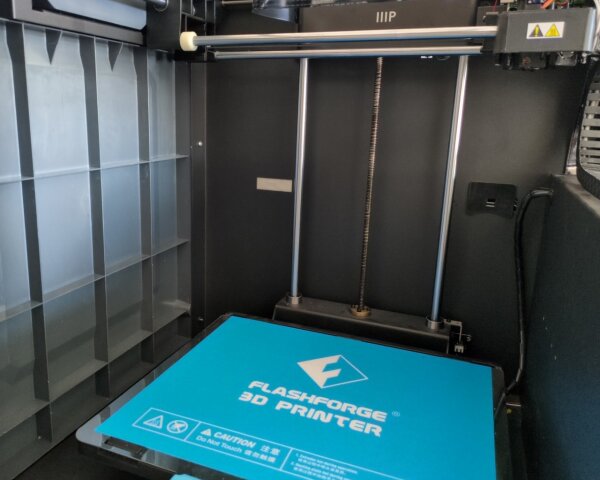
The printer is massive: with a fully enclosed build platform, strong metal frame and transparent plastic top, its dimensions are roughly 55cm x 55cm x 75cm when fully assembled and with a print spool attached. At 30-38kg total weight according to the Flashforge specs, it’s a real chonker, too.
Over time, I got less and less satisfied with the printer’s performance and hardware/software limitations of the closed proprietary system (more on this later), so I set out do a number of custom hardware modifications on it. For multiple years, this consisted of partial improvements to individual components as well as research on the original mainboard control PCB, firmware and other parts. Recently, I finally decided to drop all that and go for a radical redesign. By replacing and rewiring basically all electronics including the mainboard, I was able to convert the printer to a modern Klipper-based open source firmware setup and add a number of significant new capabilities.
Some words of warning: I do not recommend buying variants of this printer in 2024, either for unmodified usage or for a Klipper conversion, due to reasons I’ll outline along this journey. If you’re interested in advanced tinkering and tuning of settings and hardware, you’re probably better off buying & building a Voron parts kit for example, where replacement parts, upgrades and documentation are much easier to come by. If you want cheaper DIY options, consider getting at least a printer that can “natively” be converted to a modern open firmware like Klipper without ripping out all electronics. Going down this path with the Guider II comes with a lot of extra effort and costs.
If you absolutely want to do this anyway, take a look here to get some context on the hidden hardware upgrade variants, since that’ll make a difference along the way. Unless you have a lot of free time and access to cheap Klipper-compatible parts, buying a more modern and open/hackable printer will still be much cheaper and easier.
Disclaimer: I also want to stress that modifications to any 3D printer come with a serious risk of electrical problems, fires, crush injuries, and other health hazards. This set of blogposts is not a tutorial or guide, just a collection of notes, which aren’t meant to be complete or tested enough to be followed blindly. Do any changes at your own risk. Expect them to burn your house down 🔥. You have been warned!
General Printer Design
My particular printer unit began its life re-branded as a Monoprice MP Education Guider II when the original owner bought it in early 2020 at reduced clearance sale price. Except for the special firmware, it was essentially a relabeled Guider II by Flashforge, and I was able to cross-flash to the standard vendor firmware and use the Flashforge-provided flashprint slicer software under Linux.
Engineering-wise, the Guider II is arguably a high-end consumer printer design, but one from 2017. I’ll come back to this point later, because it influences a lot of modding topics. The state of the art of 3D printers has advanced significantly since then, and the resulting gap is hard to overlook in 2024.
All 3D printers are complex bundles of at least two dozen different engineering problems, heavily constrained by price pressure on the finished product.
For the Guider II, the designers decided to spend extra money on:
- Robust mechanics - dual linear 10mm diameter rods on all axis, cast aluminium mounting parts
- Large build volume
- Enclosed print chamber
- Heated bed - notably, driven by 24V DC and not mains voltage (120V / 230V AC)
Mean Well500W 24V power supply - this is a reputable manufacturer- Full Linux system + 32 bit microcontroller
- Network connectivity - Ethernet and Wifi allow network print jobs without SD cards
- Color TFT display + touchscreen interface
- Bed probe in the gantry head - for assisted manual bed leveling
- Direct extruder
Each of those drives the price up compared to simple low-end designs, for example through material costs, software complexity and higher shipping costs.
Notably, the Guider II
- Is limited to 240°C maximum extruder temperature
- Is incompatible with abrasive filaments due to its PTFE tube, brass nozzle, non-hardened extruder wheel etc
- Doesn’t have any camera to watch the print remotely (would have been possible via its existing Linux system and network connection)
- Doesn’t have any carbon air filter system
This prevents its usage with certain more advanced materials, or greater comfort / control while printing. For a model targeted at “industrial-grade” usage (according to advertising), those are obvious limitations.
Likely for those reasons, Flashforge improved upon this design with the Guider IIs hardware variant that came to market in ~2018. This variant carries over a lot of the Guider II parts, but has some additional improvements. Somewhat confusingly, there’s a second “2020” or “V2” variant of the Guider IIs manufactured from 2020 onwards, which has additional major hardware improvements and incompatible parts, but didn’t get a new model number.
On top of that, Flashforge apparently used some newer parts for later production models of the plain II series, leading to many different actual hardware configurations in the wild. This is relevant for modding and general purchase decisions.
Here’s an incomplete, speculative overview of the variants I’ve seen so far:
| Guider Variant | Components | Notes |
|---|---|---|
II early production, mid-2017 |
Mainboard V0.5, glass door |
|
II 2018-2019 |
Mainboard V0.5, plastic door, extruder PCB V0.3 |
My device |
II mid production (?) |
Mainboard V0.5 (?), new aluminium mounting parts |
seen on Bresser Rex II photos |
II mid production (?) |
Mainboard V0.5 (?), different build plate holder, new aluminium mounting parts |
seen on Bresser Rex II photos |
II late production (?) |
Mainboard V0.5 (?), flexible build plate, different build plate holder, new aluminium mounting parts |
seen on Bresser Rex II photos |
II mid-2020 |
Mainboard V0.6, different build plate holder, new aluminium mounting parts, still with A4988 drivers, extruder PCB V0.4 |
|
IIs |
Mainboard V0.5, air filter + fan, camera, new aluminium mounting parts (?) |
|
IIs "2020"/"V2" |
Mainboard V0.6, high-temperature (HT) 300°C all-metal hotend with incompatible parts, air filter + fan, camera, hardened extruder parts, flexible build plate, different build plate holder, new aluminium mounting parts, new TMC2100 stepper driver modules for X + Y + extruder |
Sources: (click to unfold)
- flashforge-au.com product description
- Reddit post “Guider II vs IIs Parts?” - note, some information likely incorrect
- Partsbuilt.com TMC2100 stepper and Partsbuilt.com Allegro stepper listing details
- Robo E3 Pro Quick Start Guide
- Privately provided photos
The backwards compatibility of using the various improvement parts with to the original Guider II is somewhat unclear. In many cases, it’s more of a “potentially yes, but not really practical” situation since they the necessary parts are not sold individually, only available at an unreasonable price, require replacement of multiple other major parts, or would not fully work with the stock firmware.
Based on my background research, the Flashforge Guider II variants were also sold under other brands such as Bresser Rex II (but not T-Rex II), and the Guider IIs variants under Robo E3 Pro, likely under a similar whitelabel deal with different labels and colors. I’m not really clear on the specific sub-versions though, and it’s possible those included multiple different hardware versions or upgrade steps as well.
In addition to a number of design flaws and problematic decisions that I’ll describe in a later post, some fundamental mechanical parts of the printer are also now fairly dated in 2024. The cartesian stepper design with independent X- and Y-axis, which moves the X-motor along with the printhead, is no longer ideal for a high-end printer. A CoreXY design that keeps both the X- and Y-stepper motor in a fixed position is a superior design for performance, considering the reduced moving mass allows for faster accelerations and prints.
In the Z-axis, the Guider’s vertically moving print bed in combination with fixed-height X/Y stage is not clearly better or worse than other configurations which keep the print bed in place at the bottom. However, its one-sided print bed mount and single active Z-stepper setup is inferior in my experience. Other printers with multiple mechanical attachment points for the print bed and multiple independent Z-stepper motors are clearly better here, since they allow automated bed leveling, as opposed to the tedious and poorly implemented manual leveling on the Guider, particularly on its stock firmware.
The lack of a resonance compensation (also known as input shaper) or extruder pressure compensation (pressure advance, linear advance) on the official firmware & mainboard is also a major downside of the older system when compared to modern designs, and limits print quality at higher speeds.
Less-invasive Printer Mods
In this first part of the series, I’ll describe some hardware modifications I’ve done to the original printer.
Flexible Build Plate Replacement
This is an “official” modification, provided as a kit (shop link, may become unavailable) by Flashforge and affiliated online shops. It’s one of the few improvements from the later-produced IIs and II variants one can officially buy and apply to II model variants that didn’t have it from the factory. The original setup consists of a glass plate above the heater element, and a textured blue sheet that’s held in place by adhesives. The kit swaps the print sheet with the provided adhesive magnetic sheet and metal print plate. This gives you the ability to remove a particularly well-sticking or large printed model from the printer together with the PEI plate, and separate the two by flexing the plate, without having to aggresively scrape or force the printed part.
For my printer variant, it was necessary to buy and replace the outer printing bed mounting bracket as well to make the new plate fit. Since there are installation videos explaining this process, I won’t go into further detail on it.
This is a useful quality-of-life improvement, but not groundbreaking.
Stepper Driver Replacement
One of my main concerns with the Guider II is the intense amount of noise it produces, even with everything closed up (front door / top cover). There are a handful of separate noise sources responsible for this that I’m trying to tackle individually.
The stepper motors are a major source of dynamically changing loudness and pitch during a print, and were high on the priority list to improve. For steppers, a this noise depends a lot on the details of how they’re driven electrically.
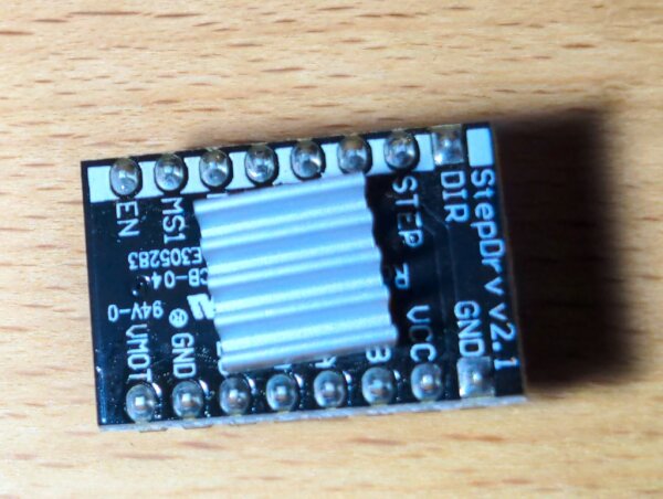
StepDrv v2.1 driver module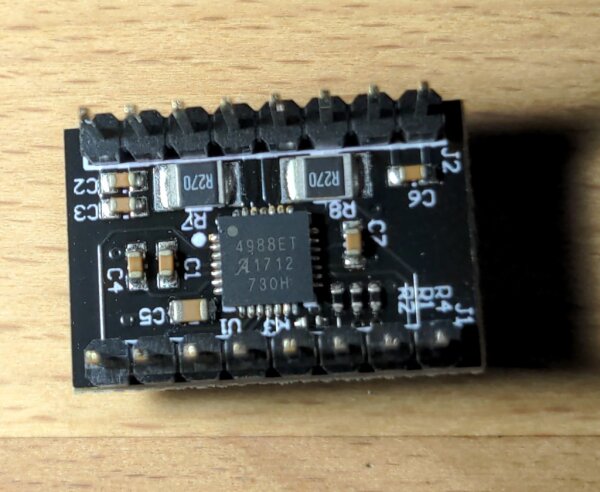
A4988 chipThe Guider II uses Allegro A4988 stepper model drivers, which are an old design. Among 3D printers, the more silent and efficient stepper drivers by Trinamic (now bought by Analog) have become somewhat of a new standard, so they’re the obvious upgrade path from Allegro.
Some models of the Trinamic series like the TMC2208 and TMC2209 are designed to have configuration modes where they’re drop-in compatible with the Allegro drivers, while running with improved modes like StealthChop2 or SpreadCycle. The driver modules on the Guider II mainboard are located on pin headers and can be swapped without soldering, which is a good design choice. Unfortunately, the Flashforge engineers mounted the original drivers in a flipped configuration that is is different from how most standard replacement modules for other printers are designed, which complicates this modification.
I wasn’t the first person to come up with this modification, so you can find more information on it in different forums.
As outlined in this Reddit post, my modification involved:
- Buy TMC2209 modules without pre-soldered pin headers
- Solder the pin headers “upside down” to the usual orientation to allow flipped module usage, leaving out pins as required
- Adjust the vRef potentiometers to limit max motor current, dependent on their specs
- Rewire the stepper driver cables to bring the motor direction in line with firmware expectations
This allowed running the new drivers with the stock firmware.
I used the TMC2209 Silentstepstick boards, the documentation on which can be found here. In the configuration I chose for step 2, I’ve left the SPREAD pin and both PDN_UART pins unconnected by not soldering in the corresponding pin headers. The DIAGand INDEX pins are also not connected, since the mainboard does not expect them.
Step 3 will require adjustments after initial installation to measure the vRef.
Step 4 can be done without fully re-crimping the stepper cables. Carefully remove all four pins from the PH connectors non-destructively by bending their metal holding tabs inwards, restore the tabs to their former angle for re-use, and then re-insert them in a new configuration. Reversing the wiring order from a 1-2-3-4 pinout to a 4-3-2-1 pinout worked for me.
Please read up on the relevant datasheets and pinouts, double-check the reasoning, and only do this modification if you understand the involved technical details and risk. I provide no guarantees here.
Be careful with any heatsinks on top of the chips, since they weren’t meant to go on this side of the PCB and there is a risk of shorting the metal heatsink against some other smd component or header pin right next to it. Having a heatsink is a good idea for heat removal from the drivers, though, especially in higher ambient temperatures.
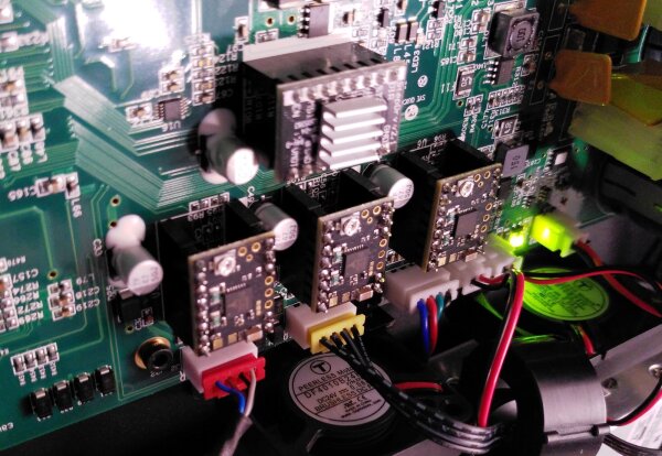
For my printer, I did this modification for the X-, Y- and Z-axis drivers (bottom row), but not for the extruder driver (top module). Replacing the latter may also be possible on the stock firmware by re-wiring the extruder stepper cable in the extruder head (see here for a photo of the carriage), but I didn’t try this with the original firmware, so don’t have any first-hand experience with it. I later used a TMC2209 driver to power the extruder from my new printer mainboard, so I don’t see an immediate technical obstacle.
Flashforge appears to have had a similar idea of using the newer TMC drivers later in their production run. According to another user in the previously mentioned Reddit post on the silent stepper driver mod, some newer Guider IIs variants ships with TMC2100-based driver modules. On these printers, DrvTMC2100 modules are installed for the X-, Y-, and extruder-stepper positions right from the factory, but notably not for the Z-stepper. While today’s newer TMC2209 driver hardware is again better than the TMC2100 driver used here, it is likely a less noticeable upgrade compared to the A4988.
It’s currently unclear to me if there are wiring- and firmware behavior changes for the stepper drivers between the V0.5 and V0.6 mainboards, and if the DrvTMC2100 modules are backwards compatible with V0.5 and corresponding firmware versions. One important topic here is motor direction. According to feedback from other users, some V0.6 mainboards were still shipped with A4988 stepper modules on all positions from the factory, which suggests there is some form of compatibility between the two, or configuration flags in the firmware.
I haven’t looked into this topic more in depth as it’s no longer relevant to my machine.
Read on in part two of the 3D printer series.
Appendix: Part Numbers
This is a collection of hardware part identifiers, which could be useful to someone looking into this system or potential replacements.
My Unit
Part information from my standard Guider II that’s a relatively early production model. Newer II and IIs variants have some switched parts.
Based on factory date markings, my printer was manufactured sometime in 2018 or early 2019.
| Description | Vendor and Part ID | Notes |
|---|---|---|
| ARM system-on-a-chip (SoC) with Linux | Nuvoton NUC972DF62Y | |
| ARM 32-bit microcontroller | ST STM32F103RCT6 | |
| eMMC NAND flash | SanDisk SDIN-502-4G | 4GB capacity |
| SPI flash | Winbond W74M32FVSSIQ | SOIC-8 package |
| TFT LCD driver | Solomon Systech SSD2828QN4 | |
| Wifi module | Realtek 8188EUS | |
| USB hub | SMSC USB2514B | |
| 10/100Mbit Ethernet Transceiver | IC IP101GR | |
| AC->DC power supply, 24V | Mean Well RSP-500-24 | |
| 40x40x10mm motherboard fan, 24V | Peerless Motors DF4010B24H | |
| 30x10mm extruder hotend fan, 24V | Ruiapple DC3010HB24 | |
| 50x15mm extruder part cooling fan, 24V | Ruiapple DB5015HB24 | |
| Extruder stepper motor, Nema 17 | Bohong Stepping Motor 42HB40F08AGW | |
| X-axis stepper motor, Nema 17 | Bohong Stepping Motor 42HB34F105AB-03 | |
| Y-axis stepper motor, Nema 17 | Bohong Stepping Motor 42HB62F2ABD-01 | |
| Z-axis stepper motor, Nema 23 | Bohong Stepping Motor 57HB41F102ASG-06 | |
| Belt | S2M880 | |
| Belt | S2M840 | |
| Linear bearing | LM-10UU |
Other Units
Some part numbers that are different from mine, based on photos of other models. This list is not exhaustive.
Guider II, v0.6 mainboard:
| Description | Vendor and Part ID | Notes |
|---|---|---|
| ARM system-on-a-chip (SoC) with Linux | Nuvoton NUC972DF61Y | |
| eMMC NAND flash | FORESEE FEMDNN008G-08A39 | 8GB capacity |
| Extruder stepper motor, Nema 17 | Hemotors HEM-17D4402-61 | |
| Z-axis stepper motor, Nema 23 | 23HD0216Z-404N-500 |